Apr 18, 2024 | News
In fluid control systems, precision and efficiency are paramount. Butterfly valves, known for their versatility, ensure consistent flow management across various sectors. The GGG50, extended stem, and concentric disc butterfly valves stand out among their peers. To assist in your selection, an examination of their characteristics, uses, and distinctions is presented, tailored to your specific flow control requirements.
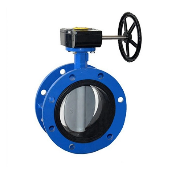
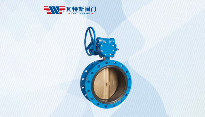
GGG50 Butterfly Valve: Precision in Performance
Crafted from high-grade ductile iron, the GGG50 butterfly valve is renowned for its robustness and corrosion resistance. Its design features a disc mounted on a central axis, allowing for precise fluid control. Employed across water networks, HVAC, and various industrial settings, the GGG50 valve excels in moderate pressure and temperature conditions. Chosen for its adaptability and longevity, it serves a spectrum of industrial applications.
Design and Operation
A GGG50 butterfly valve consists of a circular disc (the “butterfly”) mounted on a rotating shaft or stem, which is perpendicular to the flow path. When the valve is open, the disc is rotated parallel to the flow, allowing fluid to pass through with minimal obstruction. In the closed position, the disc is turned to a position perpendicular to the flow, effectively blocking it. The disc tightly seals against a durable EPDM, NBR, or equivalent elastomer seat, guaranteeing leak-proof closure in the valve’s inactive state.
Compactness, lightweight design, swift operation, and reduced maintenance needs – attributes that render these valves highly preferable over alternative types. Furthermore, they inherently offer bidirectional flow cessation, thus proving ideal for systems experiencing reversed flow directions.
Proper Usage of GGG50 Butterfly Valves
Installation
- Installation directed by flow markings or instructions: Valve correctly oriented.
- Misalignment stress prevented: Valve-to-pipe alignment kept proper to safeguard valve body and seals.
- Valve support provided sufficiently: Strain on valve-to-pipe joint minimized, seating surface integrity maintained, especially for larger valves.
- Flange connections: Use appropriate gaskets, bolts, and torque values in accordance with the valve and pipeline specifications.
Operation
- Manual operation: Depending on valve design, it’s rotated clockwise or counterclockwise for valve opening or closing. Excessive force is prohibited; leverage tools are only used when specifically suggested by the manufacturer.
- Valve operation through actuation: When fitted with an electric, pneumatic, or hydraulic actuator, the valve is operated by the control system following manufacturers’ guidelines for both actuator and valve.
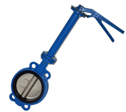
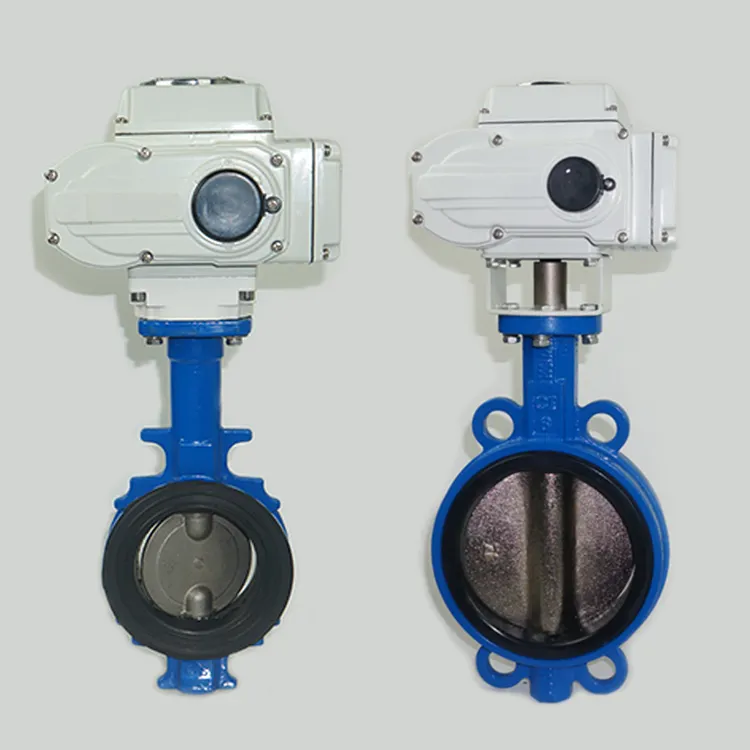
Extension Stem Butterfly Valve: Accessible Control at Your Fingertips
Extension Stem Butterfly Valve, a specialized variant of the conventional butterfly valve, is designed with an elongated stem that extends beyond the standard length, offering unique advantages and distinctive selling points for specific applications where accessibility, remote operation, or space constraints pose challenges. This innovative valve configuration combines the versatility and reliability of traditional butterfly valves with additional features tailored to meet the needs of complex or unconventional installations.
Product Description
An Extension Stem Butterfly Valve incorporates all the fundamental components of a standard butterfly valve, including a resilient-seated or metal-seated disc, a robust valve body, and a sealing mechanism. However, the distinguishing feature lies in the extended stem, which connects the valve disc to the actuation mechanism, whether manual (handwheel, gearbox) or automated (electric, pneumatic, or hydraulic actuator). The extended stem length can vary significantly, ranging from a few inches to several feet, depending on the application requirements.
What services do customers get when they purchase Extension Stem Butterfly Valve ?
- Stem lengths are customizable to suit varied space needs and installation setups, guaranteeing a precise fit for every unique application.
- Compatibility with manual, electric, pneumatic, or hydraulic actuation is provided, thus facilitating flexible control options and seamless integration into existing automation systems.
- Safety Measures Enhanced: Easy access and remote operation capabilities are enabled, passively enhancing operator safety in challenging or restricted environments, thus reducing the need for hazardous interventions to a considerable extent.
- Space Efficiency Improved: The valve body’s detachment from the actuation mechanism is a solution that passively optimizes space usage, effectively eliminating any potential interferences with surrounding structures and simplifying system layouts.
- Maintain stable performance: The reliability of the standard butterfly valve has been retained.
- Flow control efficiency is not reduced: Fluid control efficiency is effectively ensured.
- Fast response times are set to be guaranteed.
- Durability meets demanding requirements:Even in harsh applications, long service life is achieved.
Concentric Disc Butterfly Valve: Precision Engineering for Optimal Performance
The concentric disc butterfly valve is characterized by its innovative design, featuring a concentrically mounted disc that ensures precise flow control and tight shut-off capabilities. This design minimizes turbulence and pressure drop across the valve, enhancing efficiency and reducing energy consumption. Ideal for applications requiring precise flow modulation and leak-free performance, the concentric disc butterfly valve is commonly used in oil and gas pipelines, power generation plants, and pharmaceutical manufacturing facilities.
Differences and Considerations:
- Material Composition: While all three valves offer robust performance, the GGG50 butterfly valve is specifically constructed from ductile iron with a GGG50 material designation, providing enhanced corrosion resistance.
- Functionality: The extension stem butterfly valve offers extended reach for remote operation, making it suitable for applications where accessibility is a concern. In contrast, the concentric disc butterfly valve prioritizes precise flow control and tight shut-off capabilities, ideal for applications demanding high performance and efficiency.
- Applications: Each valve variant caters to specific industry requirements. The GGG50 butterfly valve finds utility in applications with moderate pressure and temperature conditions, while the extension stem butterfly valve excels in situations where remote operation is necessary. The concentric disc butterfly valve is best suited for applications requiring precise flow modulation and leak-free performance.
GGG50, extended stem, and concentric disc butterfly valves offer unique benefits for fluid management. Detailed analysis of these valves reveals distinct functional disparities. When matched with particular system demands, the ideal valve is selected, enhancing system efficiency and performance.
Apr 16, 2024 | News
Gate valves are critical to regulating fluid flow in many industries, and their efficient operation depends on careful maintenance. This guide describes maintenance methods and techniques for three gate valve categories: large gate valves, manual gate valves, and cast steel gate valves.
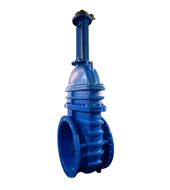
Basic introduction to Big Size Gate Valves
Big size gate valves, also called large diameter gate valves, are designed for handling voluminous fluid flows with expansive nominal diameters.These valves are essential in various industries like oil and gas transmission, chemical processing, power generation, water treatment, mining, and infrastructure projects. They handle high flow capacities, pressure thresholds, and large pipe diameters.
Selection & Maintenance
Selection:
- Selection Considerations:Working pressure, temperature, fluid properties, flow requirements, and more are considered.
- Installation & Commissioning: Strict specifications and manufacturer’s guidance are required for the installation of big size gate valves. The valve must be correctly centered, firmly supported, and connections tightly sealed and leak-free. Functional tests and sealing tests are conducted during debugging to confirm that the valve moves flexibly, experiences no jamming, and maintains a good seal.
Maintenance:
- Visual inspections should routinely be carried out to identify wear, corrosion, or damage on the cast steel gate valve.
- Suitable lubricants should be applied to the stem threads and sealing surfaces for friction reduction and smooth operation.
- Valve seals should be monitored and replaced as necessary to ensure sealing integrity and leakage prevention.
- The valve should be kept clean from debris or contaminants that might affect operation, using proper cleaning agents carefully.
- The valve’s functionality should be checked periodically, with issues like sticking or jamming addressed promptly to avoid damage.
Advantages of Manual Gate Valves in International Trade
- Adaptability to various environments: One of the characteristics of manual gate valves is their adaptability. Regardless of how adverse the conditions may be, these valves maintain their functional integrity, unaffected.
- Economic feasibility: In terms of cost management, manual gate valves are evidently favored. The initial purchase price of these valves is lower, and there is almost no energy requirement (as they do not need electricity to operate). Therefore, they can help reduce operating costs for businesses – an important consideration factor on the international trade stage.
- Ease of use and maintenance: The unique thing about manual gate valves is their simplicity.This simplicity ensures that repairs can be quickly carried out in the event of a malfunction, without the need for specialized equipment. Rapid repair turnover is crucial for preventing costly downtime in international trade operations.
- Independence from power sources: The benefits of valves that can operate without a power source cannot be underestimated. In areas with unstable power supply or frequent power outages, manual gate valves ensure the continuity of operations.
- Simple operation: Operating manual gate valves does not require extensive training or technical knowledge, making them suitable for a broader workforce. In an international context, this means fewer barriers for personnel interacting with these valves, thus making operations smoother.
- Long-term reliability: Manual gate valves are praised for their longevity. They are typically made of sturdy materials like cast steel, enduring the test of time and consistently fulfilling their duties.
- Enhanced security: In an era where digital threats are increasingly pronounced, the manual nature of these valves circumvents vulnerabilities associated with automated systems. Due to the need for physical operation, manual gate valves can effectively prevent network intrusions that might otherwise disrupt trade processes.
How to Maintain Manual Gate Valves ?
- Valve handles should be inspected regularly for wear, ensuring smooth operation and secure attachment.
- The packing gland should be checked and adjusted periodically to prevent stem leakage through proper compression.
- The valve body and parts should be coated or treated with anti-corrosion substances, especially when exposed to harsh elements.
- Valve stem and packing should be lubricated to ease operation and reduce friction, using condition-appropriate lubricants.
- Seals should be replaced when necessary to ensure ongoing sealing effectiveness and to guard against leaks, with material consideration for specific fluid and thermal demands.
Introduction and Repair of Cast Steel Gate Valve
At the heart of industrial fluid control lies the cast steel gate valve, a device synonymous with strength and precision. Built to withstand the rigors of high pressure and temperature variations, these valves are the cornerstone of heavy-duty industrial applications, from steam distribution in power plants to flow control in oil refineries.So how to make cast steel gate valves last longer? The following are some ways to maintain cast steel gate valves to extend their service life:
- Valves and their components should be observed for corrosion signs, with protective measures applied to ensure longevity.
- Inspections of the valve stem should be conducted regularly, with any abnormalities remedied quickly for uninterrupted functioning.
- Integrity checks, in the form of pressure tests, should be periodically undertaken to uncover any sealing flaws or leaks.
- To preserve performance, components like seats and discs must be replaced with authentic parts when wear is detected.
- Valve operations should be checked consistently, noting and addressing any unusual sounds, vibrations, or resistances.
By adhering to these maintenance guidelines tailored to big size, manual, and cast steel gate valves, industries can ensure the reliability, efficiency, and safety of their fluid control systems, prolonging the lifespan of these critical components and minimizing downtime. Remember, regular maintenance is key to maximizing the performance and longevity of gate valves in industrial operations.
Apr 13, 2024 | News
Wafer Dual Plate Check Valves: These little marvels are like the traffic cops of fluid flow. These nifty valves are efficient, reliable, and essential for maintaining optimal performance and system longevity. In this guide, we’ll explore the key factors to consider when selecting the best wafer dual plate check valve for your needs.
Understanding Wafer Dual Plate Check Valves
Imagine these valves as the gatekeepers of your fluid system. They go by different names—wafer double door check valves or dual plates check valves—but their purpose remains the same. Here’s the lowdown:
- Compact and Lightweight: Wafer dual plate check valves are like the minimalists of the valve world. They’re designed for tight spaces, making them ideal for applications where real estate is at a premium.
- Two Halves, One Mission: Picture two halves (plates) that swing open when fluid flows forward. But when the tide turns (literally), they snap shut, preventing any sneaky backflow. It’s like a synchronized dance routine, but for valves.
Key Considerations for Choosing the Right Valve
- Flow Rate and Pressure: Let’s talk numbers. First, assess your system’s flow rate and pressure requirements. You want a wafer dual plate check valve with a pressure rating that comfortably exceeds your system’s operating pressure. Safety first! Also, keep an eye on the flow coefficient (Cv)—it’s like the valve’s flow capacity report card.
- Material Matters: Think of your valve as a chameleon—it needs to blend in with its surroundings. Consider the fluid it’ll be handling and the environment it’ll live in. Stainless steel, carbon steel, cast iron, and various alloys are common materials. Ask yourself: Is it corrosion-resistant? Can it handle extreme temperatures? Will it play nice with the chemicals in the mix?
- Size and Fit: Size matters, especially when it comes to valves. Measure your pipe diameter and understand your flow requirements. Wafer dual plate check valves fit snugly between flanges, no extra pipe support needed. It’s like finding the perfect puzzle piece for your system.
Wafer Dual Plate Check Valves: Your Fluid Flow Guardians
In the intricate world of industries, there’s a silent hero—the wafer dual plate check valve. These unassuming valves keep the fluid traffic moving in the right direction while firmly saying “no” to any sneaky backflow. Here’s why they matter:
- Efficiency and Reliability: Think of them as the backstage crew—essential but rarely in the spotlight. These valves quietly ensure optimal performance and system longevity. No drama, just results.
- Compact and Mighty: Picture a tiny superhero. That’s the wafer dual plate check valve. It fits snugly where space is tight, making it perfect for cramped setups.

In our guide, we spill the beans on how to choose the best wafer dual plate check valve. TWT Valve always can manufacture the high quality product word-widely.
Apr 12, 2024 | News
Each type of gate valve possesses its own unique traits, almost like personalities, perfectly tailored to tackle different challenges in fluid control. In this article, we embark on a journey to uncover the quirks and capabilities of these gate valve companions, discovering where they shine brightest. From handling the gentle flow of water to the mighty rush of oil and gas, understanding the nuances between these gate valves is akin to mastering the art of orchestrating fluid dynamics in industrial symphonies. Let’s delve into the world of gate valves and explore the differences and applications of three distinct types: manual gate valve, cast iron gate valve, and non-rising stem gate valve.
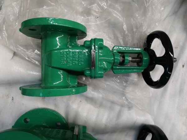
Manual Gate Valve
Design and Operation:
A manual gate valve, also known as a knife valve or slide valve, is a linear motion valve. It features a flat closure element (the “gate”) that slides into the flow stream to provide shut-off. The valve’s operation involves moving the gate perpendicular to the flow direction. Manual actuation (usually via a handwheel) controls the gate’s position.
Advantages and Disadvantages:
Advantages:
- Inexpensive and easy to maintain.
- Excellent for on-off services.
- Inherently fire-safe when used with a metal sheet.
Disadvantages:
- Poor throttling characteristics due to erosion of the seat and disk during throttling.
- Slow open and close time.
- Not suitable for sanitary applications.
Applications:
- Used in various industrial sectors, including oil and gas, pharmaceuticals, manufacturing, automotive, and marine.
- Ideal for slurries and viscous liquids (e.g., heavy oils, molasses, cream).
- Wherever a reliable shutoff valve is needed.
Cast Iron Gate Valve
Design and Features:
Cast iron gate valves are commonly made from ductile iron or cast iron. They come in both rising stem and non-rising stem designs. Rising stem gate valves have a stem that moves vertically during operation. Non-rising stem gate valves have a stationary stem, simplifying installation and maintenance.
Advantages and Disadvantages:
Advantages:
- Space-saving design (non-rising stem).
- Suitable for underground applications and ships.
- Resilient seated versions available for water treatment.
Disadvantages:
- Limited stem lubrication (non-rising stem).
- Corrosion susceptibility (non-rising stem).
Applications:
- Cast iron gate valves find use in water treatment, wastewater management, and other industrial processes.
- Non-rising stem variants are popular where vertical space is limited.
Non-Rising Stem Gate Valve
Design and Functionality:
Unlike traditional rising stem gate valves, China non-rising stem gate valves operate differently. The stem does not move visibly during valve operation. Instead, it rotates within the valve body to raise or lower the gate.
Advantages and Disadvantages:
Advantages:
- Space-efficient (no need for extra space above the valve).
- Easy installation and maintenance.
Disadvantages:
- Limited stem lubrication.
- Potential for corrosion.
Applications:
Widely used on ships, in underground installations, and wherever vertical space constraints exist. Suitable for applications requiring infrequent valve use.
In summary, gate valves play crucial roles in various industries. Whether you need a reliable shutoff, space-saving design, or specialized features, understanding the differences between these gate valve types ensures optimal selection for your specific application needs.
Apr 11, 2024 | News
Step into the realm of engineering marvels with high performance butterfly valves (HPBVs), often hailed as the enigmatic double offset butterfly valves. These masterpieces of fluid dynamics orchestrate the flow within pipes with finesse and precision. Embracing high-performance butterfly valves promises a symphony of operational enhancements, unlocking a spectrum of possibilities to optimize your fluid management endeavors.
Key aspects to enhance operations of High performance butterfly valves
Improved Process Efficiency:
Process efficiency is crucial for optimal flow capacity, minimized emissions, and reduced energy consumption. High-performance butterfly valves achieve this through several innovative features:
- Optimized Geometry: These valves are designed with field-proven technology and decades of experience. The geometry ensures smooth and efficient flow, minimizing turbulence and pressure drop.
- Reduced Energy Consumption: By minimizing flow resistance, these valves require less energy to overcome resistance. Additionally, their tight shut-off design allows the use of smaller actuators, further reducing energy consumption.
- Metal Seat Technology: Unique metal seat technology minimizes leakage, improving overall system efficiency and sustainability.
Enhanced Flow Capacity:
The heart of a butterfly valve is its disc. Even when fully open, the disc remains in the middle, affecting flow capacity. High-performance butterfly valves address this:
Two-Shaft Design: In addition to the traditional one-shaft design, high-flow capacity versions with a two-shaft design optimize flow by providing more free space in the valve flow port.
Durability and Longevity:
High-performance butterfly valves are built to withstand demanding conditions. Their robust materials and design ensure longevity, reducing maintenance costs.
Energy Efficiency:
- Reduced energy consumption due to optimized geometry and smaller actuators contributes to cost savings.
- Compressed air systems, often energy-intensive, benefit from these efficient valves.
Safety and Environmental Compliance:
- Minimized internal and external leakages enhance safety and environmental performance.
- These valves are sustainable choices, reducing the risk of failure in demanding service.
- Improved Flow Characteristics
- Reduced Wear and Tear
- Tight Shut-Off
- High-Performance Operation
- Wide Temperature and Pressure Range
- Bi-Directional Flow Capability
The eccentric design of these valves provides better flow characteristics compared to other types. The offset disc allows for a more streamlined flow of fluid, reducing turbulence and pressure drop. This results in improved flow rates and better control over fluid flow.The offset disc design minimizes wear and tear on valve components. When the valve is closed, the disc contacts only one side of the valve body, reducing friction. This extends the valve’s lifespan and reduces maintenance needs.
To encapsulate, the utilization of high-performance eccentric butterfly valves unveils a realm of precision, energy conservation, and heightened system efficacy. Harness the potential of these electrically-driven marvels to not only refine control but also to economize energy and bolster operational efficiency. Besides, integrate electric butterfly valve into your operations to elevate performance standards while concurrently curbing costs.


